
Documentation for ProTrackWarehouse 22.1.
The Facility Layout Viewer graphically displays the warehouse mapping configured within ProTrack Warehouse. This screen is also used to generate nodes on a single floor.
Info
- In order to view the Facility Layout Java applet screen, Java Runtime Environment (JRE) 1.5 is the minimum required Internet Explorer VM.
To access the Facility Layout Viewer:
- Select Facility Layout under the Standards menu. The Maintain Facility Layout screen appears.
Click
 located at the bottom-right corner on both the Manage Floor and Manage Travel Path screens.
Fig.1 Maintain Facility Layout - Show Layout
Fig.2 Facility Layout Viewer
Viewing A Facility
To view an existing facility:
- Select the facility from the drop down list.
- Select a floor from the drop down list.

Fig.3 Facility Layout Viewer - View Floor
The only way to configure XYZ-related data elements in ProTrack Warehouse is by building an import file, and importing the elements one at a time. This section refers to the spreadsheet, “SOP for XYZ Importing.xls”. This is the official document containing import templates for each XYZ component. Each tab of the workbook must be completed prior to importing the data elements.
Coordinate System Origin – Coordinate values cannot be negative, thus the origin should be set with large enough to allow floors to grow in any direction. For example, the origin could be treated as (1000, 1000). When viewing a facility’s layout in ProTrack Warehouse using the Facility Layout Java applet, the coordinate system axes are orientated such that the x-axis points to the right and the y-axis points downward. In other words, the x-coordinates ascend as you move to the right and the y-coordinates ascend as you move downward.
Location Data Element Naming Conventions – It is recommended that the following naming conventions be followed to so that the user easily knows where the data element is located on the Facility Layout.
Data Element | Naming Convention | Naming Convention Example | Comment |
|---|---|---|---|
Facility | FAC | DC1 | Facility ID must match EXACTLY what is configured in ProTrack Warehouse and being sent in the WMS extraction file. |
FAC-FLR | DC1-FLR1 | ||
FAC-FLR-AISLE | DC1-FLR1-04A | When two or more Aisle Paths are needed for a single rack (i.e. due to a non-passable barriers such as a security cage fence), append lowercase letters to the AISLE element. | |
FAC-FLR-AISLE-1 | DC1-FLR1-04A-1 | The ‘-1’ suffix increments (‘-2’, ‘-3’, etc.) with additional Segments on a single Aisle Path. | |
FAC-LOC | DC1-032457 | Must match the ‘To Location’ field EXACTLY being sent in the WMS extraction file. | |
FAC-FLR1-FLR2-1 | DC1-FLR1-FLR2-1 |
Table 1. Naming Conventions
Floor
A floor is the lowest level component of XYZ mapping. A facility can have multiple floors, which may or may not represent various actual floors in the warehouse. Floors can be used for this purpose (such as in mezzanine areas), or they may be used to simply divide a large single floor into multiple smaller sections. Any component added to the floor should be inside the floor.
Please refer to the Floor tab of the current “SOP for XYZ Importing” Excel spreadsheet.
Floor ID | Floor Name | Description | Start X | Start Y | End X | End Y | Width | Facility ID |
|---|---|---|---|---|---|---|---|---|
1-FLR1 | 1-FLR1 | Chicago - First floor | 4000 | 2500 | 8000 | 5000 | 4000 | 1 |
2-FLR1 | 2-FLR1 | Joliet - First floor | 2000 | 2000 | 6600 | 5000 | 4600 | 2 |
Table 2. Floor Example
Info
- Commas ( , ) are not allowed in description fields for any .csv import file, as ProTrack Warehouse will treat the comma as a field separator and the file will error out.
Field | Description |
|---|---|
Floor Name | Name of the floor. |
Start X | X value of the start co-ordinate of the floor. |
Start Y | Y value of the start co-ordinate of the floor. |
End X | X value of the end co-ordinate of the floor. This value should be equal to start X. |
End Y | Y value of the end co-ordinate of the floor. |
Height | This is for future development, and thus not currently available in this version of ProTrack Warehouse. |
Width | Width of the floor. |
Description | Description of the floor. |
Table 3. Floor Field Descriptions
To view a floor in ProTrack Warehouse:
- Access the Facility Layout screen, and click
 .
. Select the facility name from the Facility list and floor name from the Floor list. The selected floor will be displayed.

Fig.4 Facility Layout Viewer - Floor
Aisle Paths
An Aisle Path is a passable travel space over which equipment or people travel. An Aisle path resides on a floor and may have Segments around it. Nodes are created on the Aisle Path, at its intersections and end points. Multiple Aisle Paths can intersect.
Please refer to the Aisle Path tab of the current “SOP for XYZ Importing” Excel spreadsheet.
Aisle Path ID | Aisle Path Name | Start X | Start Y | End X | End Y | Floor ID | Bay Number Direction | Bay Number Scheme | Aisle Access Rule | Path Travel Rule |
|---|---|---|---|---|---|---|---|---|---|---|
1-FLR1-100 | 1-FLR1-100 | 4200 | 2800 | 4300 | 2800 | 1-FLR1 | ALT_LR_ES | DUB_INC | DIRECT | BD |
1-FLR1-101 | 1-FLR1-101 | 4200 | 3000 | 4300 | 3000 | 1-FLR1 | ALT_LR_ES | DUB_INC | DIRECT | BD |
1-FLR1-102 | 1-FLR1-102 | 4200 | 2800 | 4200 | 3000 | 1-FLR1 | ALT_LR_ES | DUB_INC | DIRECT | ONE_WAY |
1-FLR1-103 | 1-FLR1-103 | 4250 | 2800 | 4250 | 3000 | 1-FLR1 | ALT_LR_ES | DUB_INC | DIRECT | ONE_WAY |
1-FLR1-104 | 1-FLR1-104 | 4300 | 2800 | 4300 | 2900 | 1-FLR1 | ALT_LR_ES | DUB_INC | DIRECT | BD |
1-FLR1-104a | 1-FLR1-104a | 4300 | 2910 | 4300 | 3000 | 1-FLR1 | ALT_LR_ES | DUB_INC | DIRECT | BD |
Table 4. Aisle Path Examples
Field | Description |
|---|---|
Aisle Path ID | ID of the aisle path. |
Aisle Path Name | Name of the aisle path. |
Start X | X value of the start co-ordinate of the aisle path. |
Start Y | Y value of the start co-ordinate of the aisle path. |
End X | X value of the end co-ordinate of the aisle path. |
End Y | Y value of the end co-ordinate of the aisle path. |
Bay Number Direction | This is for future development, and thus not currently available in this version of ProTrack Warehouse. This is a mandatory field, so populate with the default value from the table above. |
Bay Number Scheme | This is for future development, and thus not currently available in this version of ProTrack Warehouse. This is a mandatory field, so populate with the default value from the table above. |
Aisle Access Rule | This is for future development, and thus not currently available in this version of ProTrack Warehouse. This is a mandatory field, so populate with the default value from the table above. |
Path Travel Rule | Denotes whether the aisle can be traveled in both directions (BD), one direction (ONE_WAY), or one direction starting from the endpoint to the start point (ONE_WAY_ES)* |
Table 5. Aisle Path Field Descriptions
Tips
- Aisle Path name and ID are recommended to be the same.
- Aisle Paths 1-FLR1-104 and 1-FLR1-104a should be two Aisle Paths as they are divided by a non-passable fence, even though they are both vertical Aisle Paths with the same X coordinates.
- Aisle Paths must be configured at 90-degree angles. Two aisle paths cannot converge at a single point and both be horizontal or both be vertical. In these cases, the two should just be treated as one Aisle Path.
- Aisle Paths cannot be built on the edge of a Floor, so make sure the Floor is larger than the location of the Aisle Paths.
To view Aisle Paths in ProTrack Warehouse:
- Access the Facility Layout screen, and click .
- Select the facility name from the Facility list and floor name from the Floor list. The selected floor will be displayed.
Select an aisle path to view the Aisle Path Properties.

Fig.5 Facility Layout Viewer - Aisle Path
A One-Way Aisle Path will be denoted by an Arrow on the aisle path. Equipment marked "One Way" will only be able to travel in the specified direction.

Fig.6 Facility Layout Viewer - Aisle Path, One Way
An Aisle Path with an Equipment Access Rule will be denoted by an orange color. Only equipment with the specified access rule will be able to utilize that aisle path.

Fig.7 Facility Layout Viewer - Aisle Path, Equipment Access Rule
Travel Paths
A Travel Path is a connection between two different floors. In the actual warehouse, this may be at a staircase, an elevator, or just any point where two floors connect. Travel paths are similar to Aisle Paths in that they are lines over which travel is calculated, but their sole purpose is to connect two floors. Travel Paths start at one node on a starting floor and end at another node on the ending floor.
Please refer to the Travel Path tab of the current “SOP for XYZ Importing” Excel spreadsheet.
travel_id | travel_name | description | start_X | start_Y | end_X | end_Y | end_ floor_id | begin_floor_id | barrier | path_access_rule | width |
|---|---|---|---|---|---|---|---|---|---|---|---|
DC1-1-2-A | DC1-1-2-A | south stairs | 1005 | 2050 | 1006 | 2050 | FLR2 | FLR1 | N | BD | 0 |
DC1-1-2-B | DC1-1-2-B | east stairs | 1500 | 1910 | 1500 | 1911 | FLR2 | FLR1 | N | BD | 0 |
DC1-2-3-A | DC1-2-3-A | service elev | 1005 | 2050 | 1006 | 2050 | FLR3 | FLR2 | N | BD | 0 |
Table 6. Travel Path Examples
Field | Description |
|---|---|
Travel Path ID | ID of the Travel Path. |
Travel Path Name | Name of the Travel Path. |
Description | Description of the Travel Path. |
Start X | X value of the start coordinate of the Travel Path. |
Start Y | Y value of the start co-ordinate of the Travel Path. |
End X | X value of the end co-ordinate of the Travel Path. |
End Y | Y value of the end co-ordinate of the Travel Path. |
End Floor Id | Floor ID corresponding to the node at the X,Y coordinate specified in the End X and End Y fields. |
Begin Floor Id | Floor ID corresponding to the node at the X,Y coordinate specified in the Start X and Start Y fields. |
Barrier | This is for future development, and thus not currently available in this version of ProTrack Warehouse. This is a mandatory field, so populate with the default value from the table above. |
Path Access Rule | This is for future development, and thus not currently available in this version of ProTrack Warehouse. This is a mandatory field, so populate with the default value from the table above. |
Width | This is for future development, and thus not currently available in this version of ProTrack Warehouse. This is a mandatory field, so populate with the default value from the table above. |
Table 7. Travel Path Field Descriptions
Tips
- Travel Paths must have some “length” to them. I.e. the start and end coordinates cannot lie on the same point.
- The start and end points specified in the Travel Path import file should intersect with Aisle Paths, thus linking two Aisle Paths on two different floors.
- Like Aisle Paths, Travel Paths MUST be either horizontal or vertical. They cannot be diagonal. This means that the Start and End coordinates must be either above or below one another, or side-by-side.
To view Travel Paths in ProTrack Warehouse:
- Access the Facility Layout screen, and click .
- Select the facility name from the Facility list and floor name from the Floor list. The selected floor will be displayed.
A Travel Path is displayed as a larger grey circle overlapping a node.

Fig.8 Facility Layout Viewer - Travel Path
Nodes
Nodes will be present at both the ends and intersections of Aisle Paths and Travel Paths. Nodes are not imported like the other components, but are instead generated via the Facility Import screen. Nodes are generated on a per-floor basis and thus must be generated for each individual floor.
Info
- Nodes are to be generated after the Aisle Paths and Travel Paths have been imported.
To generate Nodes:
- Access the Facility Layout screen, and click .
- Select the facility name from the Facility list and floor name from the Floor list. The selected floor will be displayed.
- Click
 on the properties screen.
 - Nodes will be generated and displayed on the floor.
- Click
 .
. Repeat for all Floors.

Fig.9 Facility Layout Viewer - Nodes
Segments
A Segment contains one or more locations, and thus typically represents racking. However, locations cannot exist outside of a Segment, regardless of whether or not the actual point in the warehouse is at a rack location. Segments are associated to Aisle Paths; no Segment can exist without an Aisle Path.
Please refer to the Segment tab of the current “SOP for XYZ Importing” Excel spreadsheet.
Segment ID | Segment Name | Inset | Offset | Length | Width | Orientation | Bay_Count | Number_Scheme | Number_Direction | Aisle_ID | Floor_ID |
|---|---|---|---|---|---|---|---|---|---|---|---|
1-FLR1-100-A | 1-FLR1-100-A | 1 | -2 | 98 | 4 | Left | 0 | DUB_INC | ALT_LR_ES | 1-FLR1-100 | FLR1 |
1-FLR1-104-A | 1-FLR1-104-A | 1 | -2 | 98 | 4 | Left | 0 | DUB_INC | ALT_LR_ES | 1-FLR1-104 | FLR1 |
1-FLR1-104a-A | 1-FLR1-104a-A | 111 | -2 | 88 | 4 | Left | 0 | DUB_INC | ALT_LR_ES | 1-FLR1-104a | FLR1 |
Table 8. Segment Examples
Field | Description |
|---|---|
Segment ID | ID of the segment. |
Segment Name | Name of the segment. |
Aisle Name | Name of the aisle path to which the segment is associated. |
Inset | Distance from the aisle starting point to the segment. |
Offset | Distance from aisle axis to the segment. |
Width | Width of the segment. |
Length | Length of the segment. |
Numbering Scheme | This is for future development, and thus not currently available in this version of ProTrack Warehouse. This is a mandatory field, so populate with the default value from the table above. |
Numbering Direction | This is for future development, and thus not currently available in this version of ProTrack Warehouse. This is a mandatory field, so populate with the default value in from the table above. |
Start Bay Number | This is for future development, and thus not currently available in this version of ProTrack Warehouse. This is a mandatory field, so populate with the default value from the table above. |
Number of Bays | This is for future development, and thus not currently available in this version of ProTrack Warehouse. This is a mandatory field, so populate with the default value from the table above. |
Orientation | Orientation of the Segment as it relates to the Aisle Path. This will determine which direction will be positive and negative when setting the width of the segment. Orientation of Left will have positive distances to the left of the aisle and negative distances to the right of the aisle. Orientation of Right will have positive distances to the right of the aisle and negative distances to the left of the aisle. |
Description | Description of the segment. |
Table 9. Segment Field Descriptions
In the example illustrations that follow, the blue shaded area is the segment. Each cell is 2’ by 2’, so the width of the segment is 4’. 
Fig.10 Segment Orientations
Tips
- Segments cannot intersect a node.
- Segment orientation must follow the format Left or Right, using all uppercase letters or any other format in the import file will result in the segment not properly configured.
- Locations must reside within the coordinates that the Segment occupies. Travel is not calculated from the center of the aisle to the front of the rack, so often times, centering the Segment on its corresponding Aisle Path is easiest. This can be accomplished by using Orientation = Left, Width = 4, and Offset = -2.
- When making segments in an aisle with a cross aisle in the middle, the inset should be based off the starting X,Y coordinate. For example, the racks are laid out going west to east and there is a cross aisle in the middle going south to north. The left portion will have an inset of 1 from the starting X,Y coordinate but the right portion should have an inset of the starting X to the cross aisle plus 1.
To View Segments in ProTrack Warehouse:
- Access the Facility Layout screen, and click .
- Select the facility name from the Facility list and floor name from the Floor list. The selected floor will be displayed.
Select a segment to view the Segment Properties.

Fig.11 Facility Layout Viewer - Segments
Locations & Levels
A Location is any point in the warehouse to which you want to calculate travel to or from. For example, locations may be product slot locations, product staging areas, dock doors, order pickup / drop-off locations, or conveyor drop points. Levels are optional, and represent the various heights (Z coordinate) within a particular location. Thus, levels are associated with specific locations, and so the two are imported together. All Locations must be present inside a Segment.
Please refer to the Location tab of the current “SOP for XYZ Importing” Excel spreadsheet.
Location ID | Location Name | X | Y | Floor ID | Segment ID | Level Specifier | Level Height |
|---|---|---|---|---|---|---|---|
1-loc1 | 1-loc1 | 4205 | 2800 | FLR1 | 1-FLR1-100-A |
|
|
1-loc2 | 1-loc2 | 4220 | 2800 | FLR1 | 1-FLR1-104-A |
|
|
1-loc3 | 1-loc3 | 4200 | 2900 | FLR1 | 1-FLR1-104a-A |
|
|


Table 10. Location Examples
Field | Description |
|---|---|
Name & ID | Must match. |
X | X co-ordinate of the location. |
Y | Y co-ordinate of the location. |
Floor ID | Must match the Floor ID that is configured in ProTrack Warehouse. |
Level Specifier | This is the To Location Level ID. Must match exactly what is being sent in the WMS extraction file. Each Level Specifier is separated by the pipe symbol |
Level Height | This is the distance from the floor in inches for vertical travel. Must match exactly what is being sent in the WMS extraction file. Each Level Height is separated by the pipe symbol |

Table 11. Location Field Descriptions
Info
- X, Y coordinates are entered in feet.
- There must be the same number of Level Specifiers as corresponding Level Heights.
- Be aware which direction locations will ascend/descend within an aisle on the floor and enter that same direction into the XYZs.
To view Locations in ProTrack Warehouse:
- Access the Facility Layout screen, and click .
- Select the facility name from the Facility list and floor name from the Floor list. The selected floor will be displayed.
Select a location to view the Location Properties.
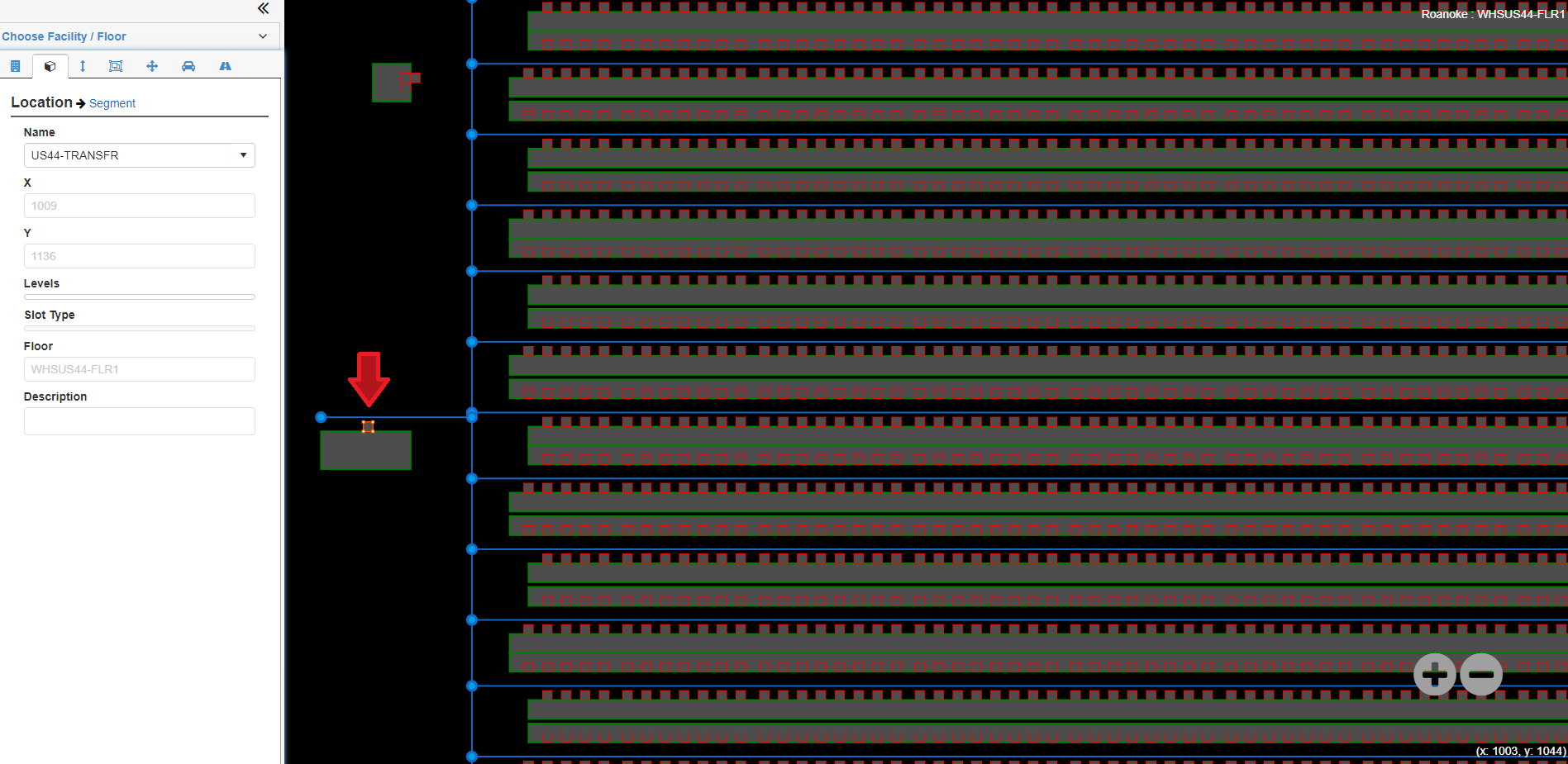
Fig.12 Facility Layout Viewer - Locations
Shortest Travel Path
The Facility Layout screen can display the shortest path between two locations given any applicable access rules.
To view the Shortest Travel Path:
- Access the Facility Layout screen, and click .
- Select the facility name from the Facility list and floor name from the Floor list. The selected floor will be displayed.
Select the "Shortest Travel Path" tab from the left pane.
- Choose a start and end location for the travel path, and apply any access rules.
- Click "Show Path." The shortest path between the locations will be displayed.
- The first figure shows the shortest path between the two locations. Note the aisle path with an access rule is not utilized, as that access rule is not being applied.
- The second figure shows One-Way travel being enforced, forcing the travel path to go around the One-Way aisle to another path.
- The third figure applies the Aisle Access Rule being enforced by the closest aisle path, allowing it for use in the travel path.


Fig.13 Facility Layout Viewer - Shortest Path

Fig.14 Facility Layout Viewer - Shortest Path, One Way Enforced

Fig.15 Facility Layout Viewer - Shortest Path, Aisle Access Rule used
Overview
Content Tools

Copyright © 2015 - present. Easy Metrics, Inc. Confidential. All rights reserved.